Sunday, May 31, 2015

Frame Ring Segments

With the middle ring cut the next step was to cut the ring segments. On the template these segments use the wood that is in the middle of the the ring. Note that four of the five segments are made out of 1/2” plywood, but the 5th, is 1/4” thick. The template says to trim it, but I will cut it out of a 1/4” piece of MDF.


The first step was to rough cut all the pieces on the band saw.


To make the outside cut I used the same router table jig that I used for the outside of the plates and middle ring. Of course these segments don’t have a pivot point so I needed to come up with a way to solve that. My solution was to use a circle I had cut out of a piece of lauan plywood when I was testing out the router table jig. I laid the circle down on top of the segment, carefully aligned the edge with the outside line and then screwed it to the circle.


With the piece attached I flipped the circle over to mount it on the router table. I made these cuts one at a time, but you could attach more then one segment at a time to the circle if you wanted to.


I probably could have adapted this jig to cut the inside edge of the segments but this edge doesn’t need to be as clean as the outside one so I decided to do the inside edges on a drum sander, just sanding down to the line by eye.


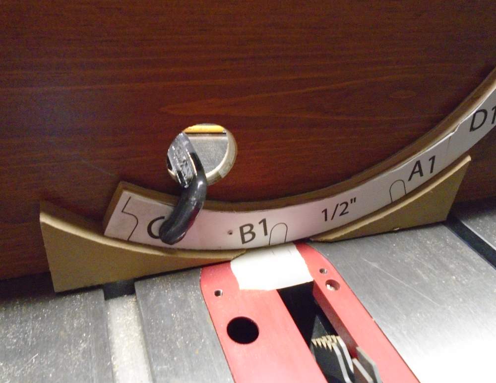
To cut the slots in the ring segments I used the same jig that I used to cut the slots in the middle ring. I did need to make one change, a large hole drilled in the plywood back piece , that I could put a clamp through to hold the segment in place.


The final steps were to trim the ends to length on the band saw, remove the templates and sand all the pieces.

Friday, May 29, 2015

Frame Middle Ring Part 2

The next step in making the middle ring for the frame is cutting the slots for the uprights. I could have used the same jig that I used to cut the slots in the top and bottom plates before cutting out the center of this one, but there are a few reasons I didn’t want to do this. First, the slots in the uprights are going to be easy to cut with square bottoms so it also makes sense to square cut these instead of having the rounded ends that the router produces. Also, since there are through cuts, I would need to setup something to hold he piece up off the bench. Finally, even if I did take that route, I would still need a way to cut the slots in the ring segment pieces later.

So to make these cuts I found an idea for a jig in another builder blog, which I can’t seem to find again. Here is my version of the jig.


The back is a large piece of plywood that is attached to the table saw’s miter gauge. Attached to the bottom of the plywood are two pieces with the same curve as the ring which support the bottom of the ring. I cut these pieces using the same router table setup that I used to cut the inside of the ring. I cut these out of a piece of 3/4” MDF.


Once the jig was assembled I installed a 1/2” wide dado blade in the saw, set it to the proper height and then carefully lined up the first slot with the blade. Once I had the slot aligned I transferred the lines for the edges of the slot to a piece of tape on the table. This will be used as a guide to make it easier to line up each slot. You will notice in the first picture that I held the ring to the jig with two springs clamps. I realized after the first cut that this didn’t hold the ring firm enough, so for the rest of the cuts I put a c-clamp on one side and a spring clamp on the other. With everything setup it was an easy process to cut all the slots.


Monday, May 25, 2015

Middle Ring


With the top and bottom plates complete I turned my attention to the middle ring. I started it the same way as the top and bottom plates, attaching the template and cutting the outside edge using my router table jig.
DSC00897
To cut the inside of the ring I needed to make an adjustment to my jig. For the outside of the ring you need to push the ring into the bit, but to cut the inside you need to do the reverse, pulling the ring into the bit. I could achieve this by moving the ring to the other side of the bit, but the clamp the held the stop block was in the way. To solve this I glued a small block to the end of the piece of wood that holds the pivot point and then clamped on a block that I could pull the stop block against. To be able to start the cut I drilled a hole that was larger then the bit, this provided clearance to start the router without the bit touching the wood.
DSC00899
Here is the completed cut.
DSC00900

Sunday, May 24, 2015

Frame Top Plate


I used pretty much the same techniques to make the top plate as I used to make the bottom. The slots for the uprights, side plates and the two narrow clearance pockets on either side were all cut the same way as on the bottom plate.
DSC00882
To do the large pocket at the bottom I used a combination of techniques. To cut the edges I went back to the router with the guide collar and some guide blocks screwed to the plate. The cut didn’t need to go all the way to the inside edge since I was going to clean that up later.
DSC00886
Next I used a router freehand to plow out most of the rest of the wood. I used a block just sitting on the work bench at the outside of the plate to keep the router level.
DSC00887
Finally I went back to my router table jig to cut the inside edge of the pocket. There was no easy way to determine where the cut starts and ends since the plate is cut upside  down, so I just made the cut slowly at either end periodically removing the plate to check how close I was.
DSC00888
After completing all these cuts I noticed that the plans for the plate show the slots for the side plates as being longer then they are in the template, so I ended up extending these slots about an inch more towards the back. The plans also show an optional hole in the middle of these slots. These holes, along with an optional slot on the side plates are used to align the top and bottom plates with the side plates. For the moment I have chosen not to do these, although I might add them later. I also have not cut the center out since I have not decided how I will mount the head yet.
DSC00948

Friday, May 22, 2015

Frame Bottom Plate Part 5


So far I have cut the small slots for the uprights, the large slots for the side plates and the two narrow clearance cuts around the edge. The next step was to cut the large clearance pockets around the edge. I handled these pretty much the same way as the large slots for the side plates, using a router with a 3/4” bit and 1” guide collar. I screwed strips of MDF around the slots to act as a guide for the router and just plowed out the area in between the guides.
DSC00879
I decided not to cut out the center park of the plate until I decide how I am going to mount the center leg. Now that all the cuts are made I scrapped off the template, patched the screw holes from where I attached the router guide block, and finally sanded everything to complete the bottom plate.
DSC00945

Wednesday, May 20, 2015

Frame Bottom Plate Part 4


The next cuts I made on the bottom plate were the two slots that hold the side plates.  Straight slots like this can normally be cut using a guide that the edge of the router plate can run against, but these are to close to the edge to be able to do that easily, so I went back to the router guide collar. These are  3/4” wide so I setup my router with a 3/4” bit and a 1” guide collar. The guide strips are just pieces of MDF that I screwed to the plate. Be sure to drill counter sunk holes for the screws so that they will be below the surface of the wood and not scratch the router base plate. To get the gap between the guides just right I attached the first one, then next to it I put a 1” block, then a couple strips of paper and finally the second guide. The pieces of paper give you just enough clearance for the guide collar to slide smoothly. For the length of the cut you could put stop blocks on either end, or just eyeball it as I did since the length isn’t entirely critical. Since these slots don’t run off the ends you will either need to use a plunge router, or just gently tip the router into the work.
DSC00878

Sunday, May 17, 2015

Frame Bottom Plate Part 3


The next slots I cut on the bottom plate were the two along the edges starting at ‘G’ and between ‘C’ and ‘B’. These slots provide clearance for body elements so the exact dimensions are not to critical. To make these cuts I went back to the router table and the jig I used to cut the outside of the plate. I adjusted the stop block so that the bit would go in to the width of the slot. I also marked the start and end of the slot on the edge since I would be making the cut with the plate upside down. The ends of the cut were a little tricky since they go in at an angle and since it’s upside down you can’t see where the bit it going, but again these cuts are not to critical. Here you can see those two cuts complete.
DSC00877

Saturday, May 16, 2015

Frame Bottom Plate Part 2


Once I had the circle cut then next step was to cut all the slots in the plate. I started with the 10 slots around the edge that hold the uprights. I was debating how best to cut these when I ran across this blog post that had a great idea for a jig to do this. Here is my version.
DSC00872
It took my three tries to get a working jig and the biggest thing I learned was the the original shape was unnecessary, a rectangular jig worked just fine.The jig is designed to be used with a router with a guide collar and a 1/2” bit.
DSC00869
The piece of wood you make the template from needs to be as thick if not a little thicker then the height of the guide collar so the collar doesn’t touch the piece you are cutting. I made the jig 12 1/4 inch long which was wide enough to get from the pivot point to a point where the router bit can get beyond the edge of the base plate. As for the width, it needs to be wide enough to allow you to clamp the template to the base plate and still leave enough room for the router to get between the clamps. For my setup 14” wide was sufficient.
Once the plywood for the jig was cut I drew a line down the center that I used to line up the pivot point at one end with the slot on the other end. The slot needs to be just wide enough to allow the guide collar to slide smoothly, but if you make it too wide you will end up with slots that are wider the 1/2 inch and then the uprights will not fit tightly. I did this by drilling four holes with a 5/8” bit and then filing the edges of the slot smooth. I ended up with a slot that was a little to wide and didn’t realize this until I had cut most of the slots on the base plate, so be sure to test your rig on a scrap piece before making your cuts.
DSC00871
Once the jig was complete I put a nail through the center hole of the base plate and into the pivot hole on the jig and positioned it so the slot was over the first notch on the pattern. All of these slots need to be 1/2” deep and you want to keep them as consistent as possible. If you can do it in one pass you will get the most consistent depth, just be sure to check the depth of your cut periodically to be sure nothing is slipping on the router.
DSC00874
I made my slots a little shorter then the template showed because I had planned to square them off. This ended up not working out well since it’s hard to chisel out the corners in plywood, so I ended up rounding the ends to the uprights a bit to get them to fit.

Saturday, May 9, 2015

Frame Bottom Plate Part 1


The first piece of the frame I built was the bottom plate which is made from a piece of 3/4” plywood. I chose to use oak veneer plywood, because the really smooth surfaces are nice to work with and it wasn’t that much more expensive the normal plywood.
I started by cutting a plywood blank a little larger then the part. I attached the template with some Elmer’s spray adhesive following the instructions for temporary attachment since I will eventually remove the template. At this point I also marked the center of the circle which will be important for a lot of the cuts. I found the center using the rectangle on the template and then verified it with a circle drawing tool.
DSC00863
The next step was to rough cut the circle on a band saw before I finished the circle on a router table. To make the finished cut on the router table required a simple jig. I cut a piece of wood that fit in the miter slot and then drilled a whole towards one end for a nail which will become the pivot point.
DSC00862
I drilled a hole in the middle of the bottom plate that was the same size as the nail, and then mounted the plate on the jig. You may want to try this out with a piece of thin scrap plywood first before cutting the actual part.
DSC00865
With the router on I slowly slid the plate into the cutter until it reached the outside line of the template at which point I backed off the piece and stopped the router. With the router off I pushed the disk back against the cutter and then clamped a second piece of wood in the miter slot to act as a stop.
DSC00880
Now that everything is setup it’s easy to cut a perfect, clean circle. Since the cut is 3/4 inch deep I decided to do it in two passes with the first only cutting about half way through. You need to be careful when doing the cut because the router is going to want to spin the disk, so you need to keep a firm grip on it. It’s also best to rotate the disk opposite the direction that the router wants to spin it. After cleaning up the edges with some sandpaper here is the disk.
DSC00867

Tuesday, May 5, 2015

Frame Plans


The first component of R5 that I am building is the body frame. I am going to build the frame from wood based on Mike Senna’s plans. You can find the plans in the Senna Files folder on the R2-D2 Builders Yahoo group. The folder called Senna Frame Prints (by M. Henricks) contains prints for all the parts with their dimensions. The file R2D2_Wood_CNC_frame_DIY rev B.pdf in that folder has some good tips for building the frame. There is also a file called SennaTemplates.pdf in the Senna Frame Prints (by M. Davis) folder. This file contains a single 36”x48” drawing of all the parts full sized which can be used to print templates for cutting he parts. One important thing to note about these templates, they do not always agree with the plans. I have found one discrepancy so far and will try to note when I find others.
Like most people I do not have access to a printer that can print a drawing that large so there are a few other options. I checked with my local Staples and they can print the drawing for $7.00 and I also found a local print shop that can do it for $3.50. In the end I decided to print them on my normal inkjet printer on multiple sheets which I then taped together to make the full size plan. This turns out to be pretty easy to do using Adobe Reader.
In the Print dialog box in Reader first select your printer and be sure the proper paper size is selected. Next under Page Size & Handling click on Poster. Be sure the Tile Scale is set to 100% and check Cut marks.
image
The finished print will not go right to the edge of the pages but the cut marks make it easy to trim each page so they fit cleanly together. I also found an option in Reader that allows you to print only what is showing on the screen. Under More Options select Current view and it will print only the section you are displaying. I did this to print each part as I was making them.
No matter what technique you use to print the plans, be sure to verify that they printed at the correct scale. The easiest way to do this is to use the slots around the edge of the top an bottom frame. These slots should be 1/2” wide.

Saturday, May 2, 2015

My Astromech Build


I was nine years old back in 1977 when I first saw Star Wars and it had a huge impact on me. I still remember getting the toys, trading cards, bed sheets, record albums (on vinyl!) and anything about Star Wars I could get my hands on. I chipped in with a couple friends to buy the novelization of the movie and we spent hours acting out scenes from the movie. I have forgotten how many times I made my parent take me to see the movie, but it was definitely the first movie I saw more then once in the theaters. I also remember my father building me an astromech droid. It didn't look like any of the ones in the movie, but it had the basic astromech shape and it was a very cool thing to have.

Today I am still a huge Star Wars fan who is eagerly awaiting the release of The Force Awakens. I also enjoy building things, whether it be model kits, sets for my local community theatre or furniture for my house. I thought it was about time to combine these two loves and actually build a life size astromech droid. This blog will document my process.

The first decision I needed to make was which droid to build. As much as I would like to build an R2-D2, I wanted something that I felt I could do as much from scratch as possible, so my plan is to build an R5-D4 because it’s head shape is easier to build from scratch.

R5d4

The next thing I needed to decide on was what materials to use. Most droids are build from some combination of wood, styrene plastic and aluminum. Since I am most comfortable working with wood, and since it’s a material that is easy to get locally I plan to build as much as possible from wood. At this point I do plan on using styrene for the skins. I have seen people use wood, but I think styrene will give it a better look.

Finally I needed to think about how much mechanization my droid will have. Some people have done very advanced levels of automation where not only can the droid move via remote control but the head can turn, arms can extend and it even go from three leg to two leg mode. At this point I think I am going to do some minimal mechanization. I would like to motorize at least the feet and head.