Friday, June 8, 2018

Foot Frame Part 1

I build the structure of the feet out of wood and eventually finished them with styrene details. In this post I will show the start of the process for building the outer feet. Here are the first three pieces cut out of plywood that form the channel where the foot connects to the leg.

DSC01442


Here you can see how the leg will connect to the foot.
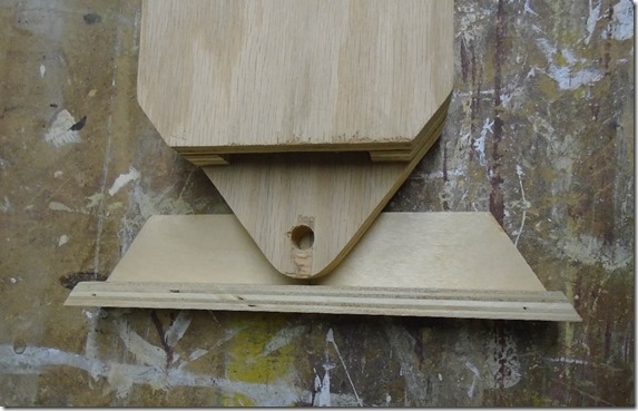
DSC01443


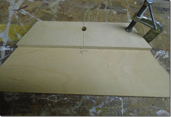
I first drilled a hole in the smaller piece that will receive a bolt to hold the foot to the leg. Next I clamped the small piece to the larger one and drilled the whole through the larger piece. Doing it this way assures that the holes are perfectly lined up.
DSC01445


On the other side of the large piece I added a t-nut that the bolt will thread into.

DSC01446


With the holes drilled I glued up the three pieces and secured them with brad nails.

DSC01447


Next is another plywood piece that will be used to support the styrene on the curved side of the foot.

DSC01448


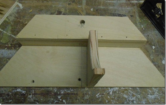
Here is that place glued in place. The two small holes at the bottom are to secure some old surplus drive units that just happened to have. More on that in another post.
DSC01449


I also created a long hole near the bolt hole that will allow the wires from the motors to be routed into the legs.

DSC01452


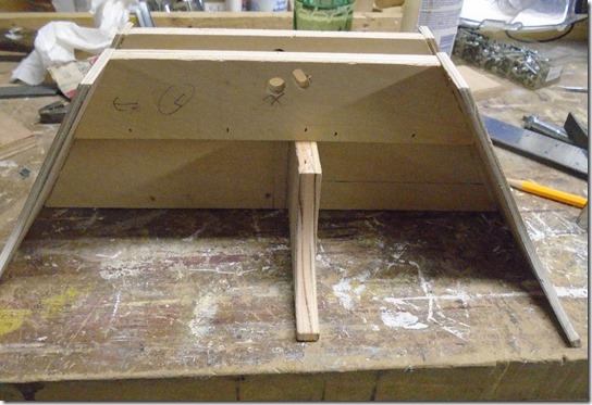
Next I cut the ends of the foot out of luan plywood. I didn’t get a good picture of them before I attached them. Before cutting the final shape of these parts I ran the raw piece on the table saw to cut the proper angle on the top and bottom of the part.
DSC01453


The next part is this block added to the back of the foot. The drive motor will go in the front section, and a caster wheel will go in the back. The block is set at just the right height for the wheel I plan to use.

DSC01456


The flat side of the foot is made with another piece of luan, so I first attached some small wood strips along the edge to better hold the side on. Here they are clamped on while the glue dries.

DSC01458


Here is the wood side glued and tacked on.

DSC01457

Saturday, June 2, 2018

Leg Strut Part 3

The final detail on the leg struct is the disk on the block at the top. I cut this out of a dowel and glued a small washer to the bottom to create the space between the disk and the block.

DSC02293

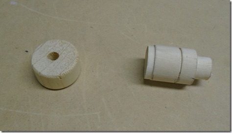
Here are all the parts prior to assembly.

DSC02294

To assemble it I started with everything but the top block so that I could clamp the whole assembly while the glue dried.

DSC02297


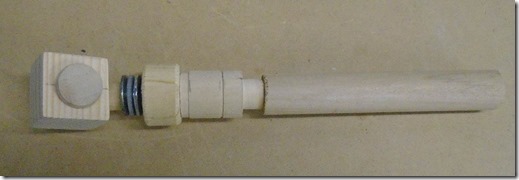
Here is the final part before paint.

DSC02338

Sunday, March 25, 2018

Leg Strut Part 2

In my last post I showed how I build section 3 and 4 of the leg strut, in this post I will show section 1 and 2.

LegStruct

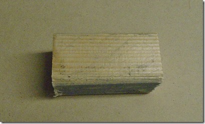
I started out with a piece of 2x2 stock, cut down the width and height on the table saw and finally cut it to length. The circle on the finished piece is to indicate which face will eventually get the disk.

DSC02283 DSC02284

DSC02286

Next I need to drill a hole for the dowel shown in section 2. Here I have marked the location where the hole will go.

DSC02287

Since this has to be drilled and an angle I made up this jig to hold the piece while I drill it. I made the hole with a forstner bit.

DSC02289

Here is the block with the dowel. Not shown here, but I also drilled a small hole in the end of the dowel for a smaller dowel which will attach it to the rest of the assembly.

DSC02292

To make section 2 I decided to use a stack of alternating sized washers. I started by making a jig with is simply a small dowel in a piece of scrap. I then put down the first large washer, and then glued on a small one using super glue.,

DSC02295

I then repeated this process with two more large and two more small washers. I put on a stack of washers (not glued) to make up the rest of the height if the dowel and then clamped the whole thing until the glue dried.

DSC02296

Saturday, March 3, 2018

Leg Strut Part 1

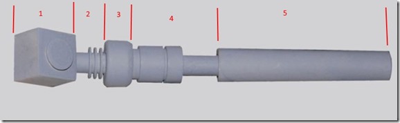
The next piece to work on is the leg strut. This is a much more complex part then the shoulder hydraulic I showed in the last couple posts, so I broke it down into 5 section as seen in the diagram. I will start with section 4.

LegStruct

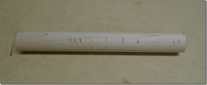
For this piece I went back to the machine lathe. I started with a dowel that matches the largest diameter of the part. Using the measurements in the plans I marked out each segment.

DSC02267

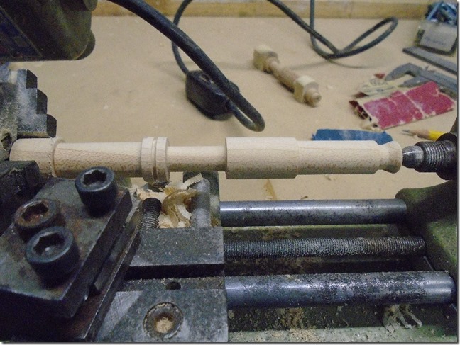
I then machined each of the grooves in the part.

DSC02268


DSC02269

Here is the part with the lathe work complete. I still needs to be trimmed to length and cleaned up a bit.

DSC02271

Using a centering gauge I marked the center of each end.

DSC02280

I then drilled out each end for dowels that will be used to connect the sections together.

DSC02281


For piece 3, I cut the part from a dowel of the correct diameter and then used a file and some sanding to create the bevel on the edges.

DSC02270

I marked the center of the piece with the centering gauge and then mounted it in my dowel drill jig to drill a hole through the center.

DSC02273

Here are the two pieced complete.

DSC02278

Monday, January 1, 2018

Shoulder Hydraulic Part 2

In my last post I showed how I did the round parts of the shoulder hydraulic. In this post I will show how I did the square parts which mount it to the horseshoe.

DSC02265-2


The first step was to cut a piece of wood to the finished dimensions of the block. The top of the block is rounded over, so to do this I ran the piece on the router table with a large round-over bit to get the slightly rounded top. Once that I was done I could cut the piece into the appropriate sized blocks.


DSC02260


Next I laid out where the hole needs to be drilled in the block.

DSC02262


I drilled the hole on the drill press. I made a fixture to hold the piece while it was being drilled but I didn’t get a picture of it.

DSC02263

These pieces can then be slid on the ends of the round part and glued in place. Here is the completed shoulder hydraulic.

DSC02266

Sunday, August 27, 2017

Shoulder Hydraulic

The next piece I needed for the shoulder was the shoulder hydraulic.

R2_Shoulder

I made this is three parts, the round central shaft and the two blocks at either end that hold it to the shoulder. To make the shaft I turned to a pretty specialized piece of equipment. This is a Unimat mini machine lathe. I rescued this one from my father’s basement where it had been water damaged. It took a lot of WD-40, rust remover and scrubbing to get it taken apart and cleaned up. I also got replacement belts from Toms Tool Store. With this tool I could have made the shaft from metal, but I am more comfortable with wood so that is what I went with.


DSC02242

I started with a dowel that matched the largest diameter of the finished part. Using the measurements of the plans I marked the location of each section that needed to be cut. Once the piece was mounted in the lathe I spun the dowel and marked the lines all the way around.

DSC02239

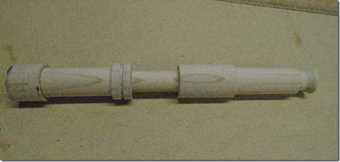
Next I used a couple different cutting bits to cut each section. I use a pair of calipers to check when the correct diameter had been reached.
DSC02240


DSC02244


DSC02246


Here is the piece after the lathe cuts had been made. For now I did not cut off the ends because I needed to put it back in the lathe later for one more cut.

DSC02247


The hardest part of making this was the knurling around the one section. I tried a couple way to do this and the technique I ended up with produced a pretty satisfactory result. To start I used a CAD program to general a series of parallel lines with the spacing I wanted for the knurling.

DSC02248

I used spray adhesive to glue the pattern onto the part.

DSC02254


I also made a block to hold the part while I was cutting the knurling. When making the cuts the tools are going to tend to come off the end of the knurled area, so I wrapped some electrical tape around the part to protect it.

DSC02256


To make the cuts I started with a straight edge and an X-acto knife. Next I used a sharp dental pick to widen each cut. Finally I used to a diamond shape needle file to get the final size and shape of each cut.

20170827_111747

With the knurls cut and the rest of the paper pattern cleaned off I put the part back on the lathe to make the groove in the middle of the knurled section.

DSC02259

I my next post I will show how I finished it.