The rear logic display is put together the same way as the front logic dispalys. There is a PCB, bezel, and a clear plastic cover. I once again used spacers between the PCB and bezel.


The logic displays are composed of three parts, the PCB, a bevel that goes around the LEDs and a clear plastic window.


To mount the Processor Status Indicators (PSI) I used a standard PVC pipe coupling. The PCB fits perfectly in these and they have a ridge in the center that will hold the board in a good spot. Also pictures here is the dome panel that goes in front of the PSI. Not shown is a frosted disk that goes on the front. I cut that disk out of a piece of white plexiglass and glued it to the coupling. The edges will not be seen so the cut doesn't need to be very clean.


The first electronic elements I added to R2 were the dome lights. I got an early start on these since I needed to figure out how I was going to mount them in the dome.
There were initially five lighting elements I worked on. On the front are the two rectangular Front Logic Displays and the round Front Processor Status Indicator.


I followed a similar process for the ankle details. These need the tab on the end to be blue and also the recessed rectangle. This required some careful masking.


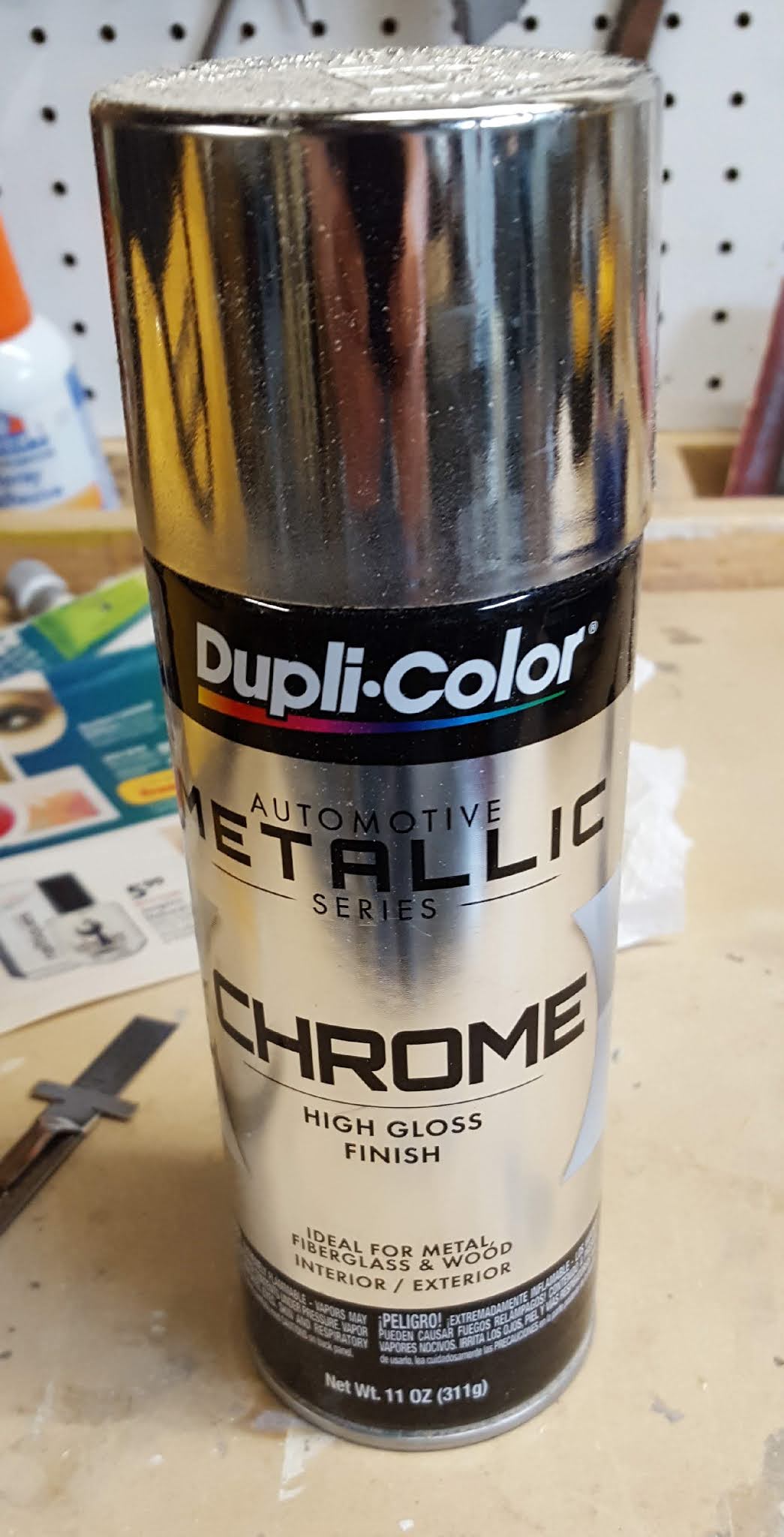
To paint R2, I used off the shelf cans of spray paint.
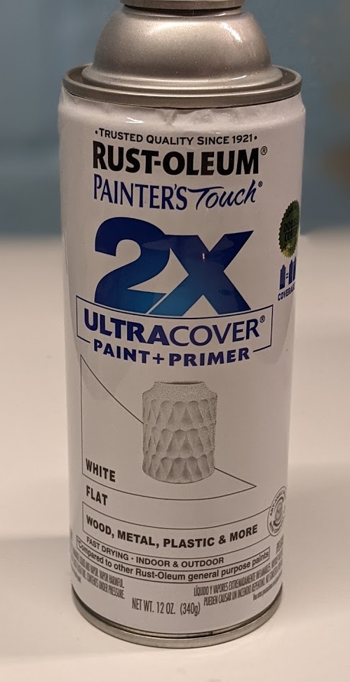
For the white parts, and as a primer for all the other parts I used Rust-oleum Ultracover Paint+Primer Flat White.


For the Radar Eye I used a resin casting I purchased online, you can find the details in this post.
The back of the part has four casing points on it that needed to be cut off. I did this with a Dremel and then did some sanding to cleanup that back.


