Sunday, February 24, 2019

Under Shoulder Detail Part 2

The part of the shoulder detail is the smaller cylinder. Due to it’s size I decided to make more then one at a time.I started with a dowel of the correct finished diameter and marked of where the cuts need to be made for each part.

DSC02341

I mounted this in the lathe and marked the lines all the way around.

DSC02342

I used the lathe to cut the low areas on the end of each part. The raised area will become knurling.

DSC02343

Once the lathe work was done I cut the pieces to their finished length.
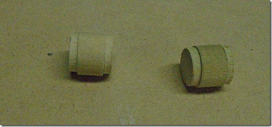
DSC02344

To make the knurling I used the same technique as the large cylinder. I drilled a hole through the part so I could mount it on this jig to make the grooves.

DSC02346

Here is the part with the knurling complete.

DSC02347

Sunday, February 10, 2019

Under Shoulder Details Part 1

The next part I am going to show is the under shoulder detail.

ILM R2 P1010009


To make the main part I started by cutting a dowel into pieces of the correct length.

DSC02348


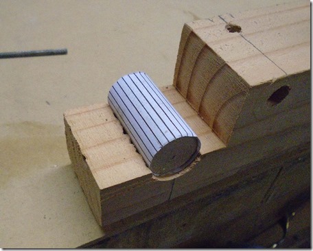
To create the knurling on the part I started by making a paper template with lines for where each groove will be. I wrapped this template around the part and glued it on using spray adhesive.

DSC02349


To hold the part while I was working on it I took a block of wood and drilled a hole in it the same size as the dowel, then I cut the end of the block in half exposing the button of the hold .

DSC02394


To make the grooves I started with an X-Acto knife and the opened up the cuts some more with a needle file.

DSC02350


These parts have a groove around them on either end. To make this I went back to my mini-lathe.  I wrapped electrical tape around the end of the part to prevent the jaws from damaging the part.

DSC02351


Finally I drilled the holes that will hold the side dowels. I went back to my jig to hold the part and drilled in on the drill press.

DSC02352

Sunday, February 3, 2019

Foot Half Moon Details

On the side of the feet is the half moon foot detail. 


 I started by cutting paper templates from the styrene plans. The middle element has some smaller pieces that I didn't do templates for but just hand cut. I used these templates to cut the styrene parts.


To make the half moon I wrapped the outer part around the half circle element and glued it in place. You need to be sure you have it carefully aligned so that both ends end up in the correct location. Next I cut and glued in the triangular ribs to strengthen the part. 


The middle element is made of three parts. The front part with the two slots at the top, two thin triangles that form the sides and finally a small strip to close up the bottom. I glues up these parts and sanded them smooth and the glues the finish assembly to the half moon.


Since the side of the foot was skinned in styrene I could use styrene cement to glue on the detail. I used a couple clamps to hold it in place to dry. In this picture you can also see the three other details on the side of the foot. These were cut from styrene using templates made from the plans and glued in place with styrene cement. 


Saturday, January 12, 2019

Ankle Cylinder Holders


The final part of the ankle is the Ankle Cylinder Holder. This is a crescent shaped piece right below the cylinder.

hd-7


To make the part I started with a template made from the plans and then traced that on a piece of 3/4” MDF. I rough cut the curve on the bandsaw and then finished it on the drum sander. The shape the template provided wasn’t a perfect fit for my ankle so I needed to do a little more sanding to get the size and shape right. On the flat side of the part is a cove that the cylinder fits into. To make this I started by removing some of the material on the table saw. I set the rip fence so that the blade will be right in the middle of the part, and set the blade to the maximum depth of the cove. After making that cut I moved the fence over one blade width and lowered the blade and made another cut on each side of the first cut. To remove the rest of the material I wrapped sandpaper around a piece of the same pipe I used for the cylinder and sanded the cove to it’s final shape.

I believe I did the crescent cut first, but in hindsight it would probably be easier to make the cove first and the cut the crescent shape.

DSC01882


To attach the part I used dowel pins just like I did on other ankle parts. I used the same method as the cylinders to mark the location of the dowels on the ankle, putting some paint on the end of the dowels and using that to mark the ankle.

20181201_134042


One of the problems with writing these blog posts so long after the work was actually done is that I have forgotten some things. I found this picture and wasn’t completely sure what I was doing here. These pieces are made from plywood, but the actual pieces I ended up using are from MDF. These are nailed together in pairs. I think I did this so that I could sand two at a time and get perfect matches. These were probably a first attempt at the part that I discarded.

DSC01755

Sunday, January 6, 2019

Ankle Cylinder Mounting


For most of the leg parts I used dowels to mount them to the leg. This allowed me to temporarily assemble the legs without having to glue things on. I will eventually glue the parts on and the pins will help align the parts and give the connection some more strength.

20181201_134136

To mount the cylinder I started with an MDF block that fit tight into the back opening. Before attaching the block I drilled two holes for the pins. The exact location of the pins isn’t critical since I have an easy way to transfer the location to the leg. With the holes drilled I used epoxy to glue the block into the cylinder.

To transfer the location of the pins to the leg I put temporary dowels into the holes that were just long enough to stick out beyond the block. Next I put a generous drop of black model paint on the end of each dowel and before the paint dried, put the cylinder in position on the leg and then pushed it down to transfer the paint to the leg. This will leave marks where I drilled the holes. Finally I replaced the short temporary dowel with the full length ones.

Sunday, December 30, 2018

Ankle Cylinder Wedges

The next part of the ankle is the wedge that goes between the cylinder and and the slopped part of the ankle.

I started by making templates from the plans and then cutting the parts out of styrene.

DSC02340


Here is the part glued together. Once the the glue was dry I wrapped a piece of sand paper around the same PVC pipe I used to make the cylinders and sanded the curve to get a good fit to the pipe. You also want to be sure to sand down the edge of the top part so it will also fit tight to the cylinder.

20181223_113827


I glued the wedge to the cylinder using model glue. I got things a little out of sequence here. You can see that I had painted the cylinder before attaching the wedge. The be sure the glue held I had to sand off some of the paint before attaching the wedge. This really wasn’t a  problem since that center section will be blue when finished anyway.

20181120_145742


I used some hobby putty to smooth out the connection between the wedge and the cylinder. I also used it on the edges to fill any place where it didn’t fit tight to the cylinder.

20181121_123900


I also used some hobby putty on the back to strengthen the connection. You can also see in this picture that I used some small strips of styrene to make it easier to attach the sides, but this wasn’t really needed and I didn’t do it on the later pieces.

20181120_150217

Sunday, December 23, 2018

Ankle Cylinder End Caps


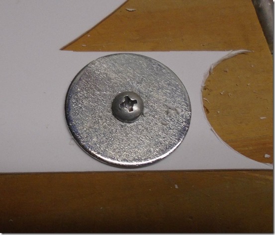
To make the end caps for the ankle cylinders I needed to cut styrene disks. To cut the disks cleanly I found a metal washer that was the correct diameter which I screwed through the styrene to a block of wood. I then used an X-Acto knife to cut out the disk.

DSC01870

Here are the finished disks. The hole in the middle will be covered by the tabs that go on the end on the cylinder.

DSC01871


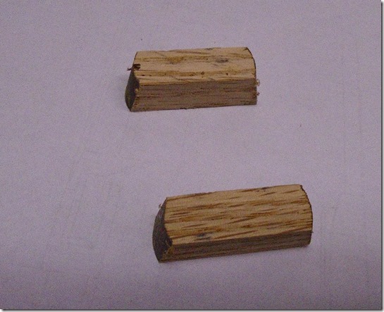
To make the tabs I started with a piece of oak cut to the correct height and width, I then cut the individual pieces to the correct length. To get the angle and round over on the end I use my small belt sander.

DSC01872


DSC01877


Here is the end cap with everything glues together.

DSC01878