The next step on the outer feet was to do that styrene pieces on the top of the foot. I cut the pieces larger then needed, glued them on with White Gorilla Glue and taped them in place.

Once this was dry I used a Dremel to sand the styrene flush.
The next step on the outer feet was to do that styrene pieces on the top of the foot. I cut the pieces larger then needed, glued them on with White Gorilla Glue and taped them in place.
Once this was dry I used a Dremel to sand the styrene flush.
The next step in building the feet was to do the styrene skins. He is a picture of the initial state of the foot. The screw at the top are going to be used to hold the battery boxes, I removed them before starting to attach the skin.
For the curved side I place a piece of styrene tight to that side, traced the shape and then cut it larger then needed. To glue the piece on I used two-park epoxy. I generally use epoxy when the joint needs to be strong and there is a small surface to glue to, both of which are a concern for this part. Initially I just glued the styrene to the large flat area at the top since it was easy to clamp this firmly. Once that part dried I lifted the skin, and applied epoxy to the remaining surfaces. The trickiest part of this was hold the skin until it dried.
As you can see in the following pictures I used a combination of clamps, tape and even a spray paint can to hold the skin tight to the frame.
Once the glue was dry and I removed the clamps I applied some more epoxy along the seams on the inside of the foot to further strengthen in.
Here is what it looks like after unclamping. I next used a Dremel to sand the styrene flush with the frame.
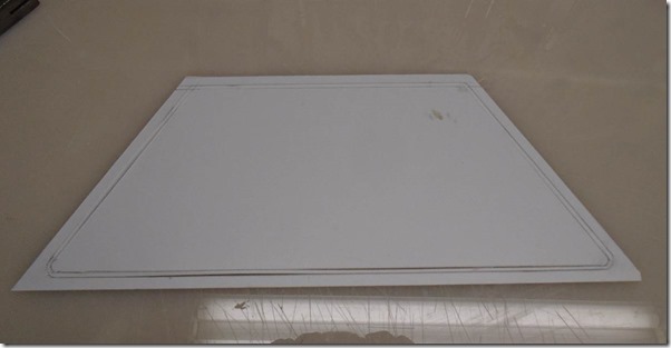
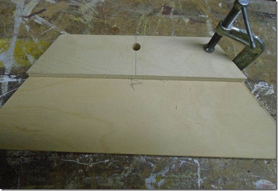
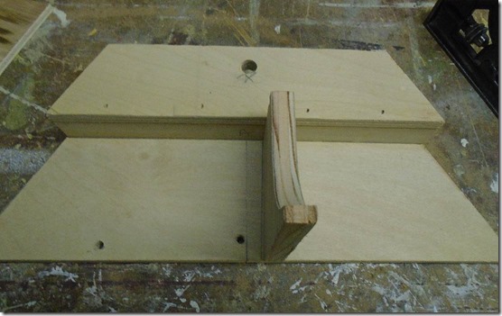
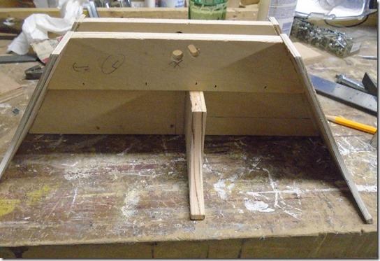
The skin on the flat side of the foot was much easier. Here you can see the piece with the layout marks. The area between the lines needs to be cut out to form a groove. I first tried doing this cut after gluing the piece in place, but it turned out to be much easier to make the cuts ahead of time.
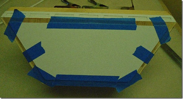
I started by gluing the inside piece first. Since this piece has a large surface area I used White Gorilla Glue for this. I used tape to prevent it from sliding until I could get some clamps on.
Once that was dry I attached the outside part using epoxy which I find holds better with the smaller surface area. I don’t have pictures of that.
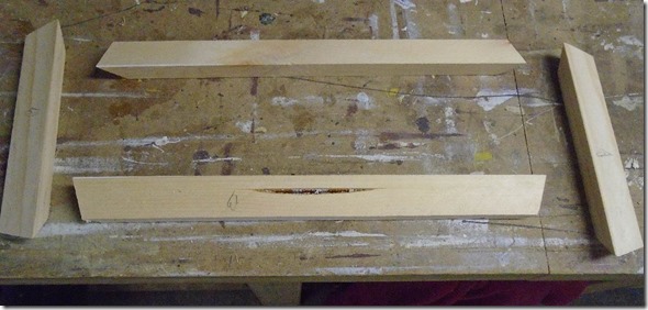
The next part of the feet is the trim piece along the bottom. I started this with a piece of pine cut on the table saw to the right thickness and angles.
I glued these pieces together and used some small nails in a nail gun to tack them together.
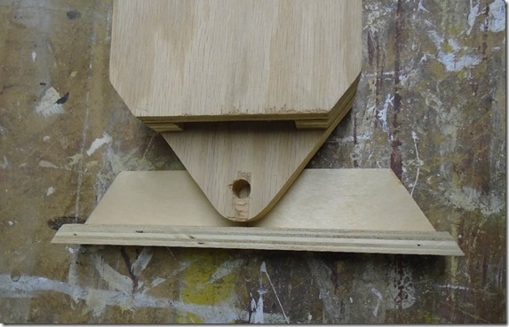
Once the glue was dry I glued them to the bottom of the foot shells I showed in my last post. I put two thin screws into the center plywood web to hold the trim on until the glue dried.
With the frame complete I started on the details along the bottom part. Below you can see the paper template I cut from the full sized plans.
I then used that template to markup the styrene for the part.
Finally I cut out the part. Two important notes about doing this. First I cut out the rectangular areas first before cutting it off the sheet because it makes it easier to hold the part as you cut. I also left the piece long on both ends and will cut it to size later so I am sure if fits the foot properly.
I could have attached this piece directly to the foot, but I found it was easier, and provided a cleaner result if I first glued this to a very thin piece of styrene and then glued the entire assembly to the foot. Here is the part being glued to the backing.
Here it is being glued to the foot shell.
Here is the foot shell with the trim pieces all attached. For the corners I used styrene glue to attach the pieces together and the sanded them smooth.
I build the structure of the feet out of wood and eventually finished them with styrene details. In this post I will show the start of the process for building the outer feet. Here are the first three pieces cut out of plywood that form the channel where the foot connects to the leg.
Here you can see how the leg will connect to the foot.
I first drilled a hole in the smaller piece that will receive a bolt to hold the foot to the leg. Next I clamped the small piece to the larger one and drilled the whole through the larger piece. Doing it this way assures that the holes are perfectly lined up.
On the other side of the large piece I added a t-nut that the bolt will thread into.
With the holes drilled I glued up the three pieces and secured them with brad nails.
Next is another plywood piece that will be used to support the styrene on the curved side of the foot.
Here is that place glued in place. The two small holes at the bottom are to secure some old surplus drive units that just happened to have. More on that in another post.
I also created a long hole near the bolt hole that will allow the wires from the motors to be routed into the legs.
Next I cut the ends of the foot out of luan plywood. I didn’t get a good picture of them before I attached them. Before cutting the final shape of these parts I ran the raw piece on the table saw to cut the proper angle on the top and bottom of the part.
The next part is this block added to the back of the foot. The drive motor will go in the front section, and a caster wheel will go in the back. The block is set at just the right height for the wheel I plan to use.
The flat side of the foot is made with another piece of luan, so I first attached some small wood strips along the edge to better hold the side on. Here they are clamped on while the glue dries.
Here is the wood side glued and tacked on.
The final detail on the leg struct is the disk on the block at the top. I cut this out of a dowel and glued a small washer to the bottom to create the space between the disk and the block.
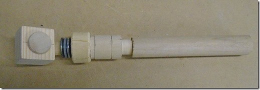
Here are all the parts prior to assembly.
To assemble it I started with everything but the top block so that I could clamp the whole assembly while the glue dried.
Here is the final part before paint.
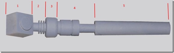
In my last post I showed how I build section 3 and 4 of the leg strut, in this post I will show section 1 and 2.
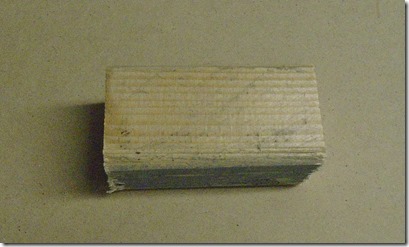
I started out with a piece of 2x2 stock, cut down the width and height on the table saw and finally cut it to length. The circle on the finished piece is to indicate which face will eventually get the disk.
Next I need to drill a hole for the dowel shown in section 2. Here I have marked the location where the hole will go.
Since this has to be drilled and an angle I made up this jig to hold the piece while I drill it. I made the hole with a forstner bit.
Here is the block with the dowel. Not shown here, but I also drilled a small hole in the end of the dowel for a smaller dowel which will attach it to the rest of the assembly.
To make section 2 I decided to use a stack of alternating sized washers. I started by making a jig with is simply a small dowel in a piece of scrap. I then put down the first large washer, and then glued on a small one using super glue.,
I then repeated this process with two more large and two more small washers. I put on a stack of washers (not glued) to make up the rest of the height if the dowel and then clamped the whole thing until the glue dried.
The next piece to work on is the leg strut. This is a much more complex part then the shoulder hydraulic I showed in the last couple posts, so I broke it down into 5 section as seen in the diagram. I will start with section 4.
For this piece I went back to the machine lathe. I started with a dowel that matches the largest diameter of the part. Using the measurements in the plans I marked out each segment.
I then machined each of the grooves in the part.
Here is the part with the lathe work complete. I still needs to be trimmed to length and cleaned up a bit.
Using a centering gauge I marked the center of each end.
I then drilled out each end for dowels that will be used to connect the sections together.
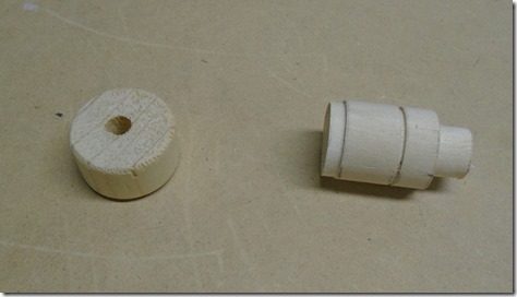
For piece 3, I cut the part from a dowel of the correct diameter and then used a file and some sanding to create the bevel on the edges.
I marked the center of the piece with the centering gauge and then mounted it in my dowel drill jig to drill a hole through the center.
Here are the two pieced complete.